
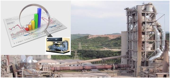
Compressor Performance and Optimization
Conclusion: Periodic and punctual assessment by using shop floor methods and routine maintenance of compressor and compressed air network is essential to ensure optimized production cost and early attempt to harvest optimization opportunities. So, it is recommended highly to audit your compressor section/network by an expert once and follow the standard operating procedures to sustain a controlled optimum operation.
Objective of Article Publication:
- This paper is published with a goal to help operators, Engineers and auditors to contribute to global cause of energy conservation and environment protection by saving a slice of energy loss along with creating value (profit) for industrial businesses and customers.
- To make reader sufficiently capable to audit compressor and compressed air system in an industry like cement plant etc.
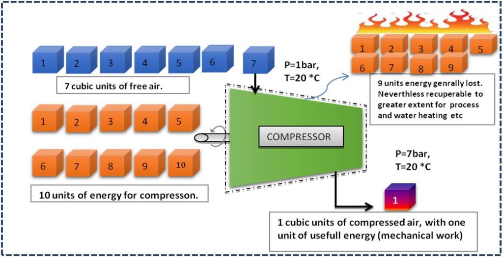
Compressed air is an essential utility in numerous process industries in the value stream (process) of manufacturing valuable products. But in reality compressed air is very expensive utility because only 10-30 % of energy invested reaches the point of end-use and the balance of 70-90 % is wasted (generally) in the form of heat, friction, noise and misuse.
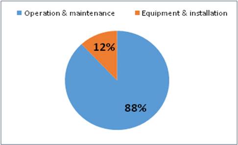
Moreover to highlight the fact, for an air cooled compressor over 10-years of life with two shift operation, the operation cost for electricity and maintenance is equal to 88% of total life time cost and the balance of 12% is made up of installation and original equipment cost.
Regarding compressed air as a utility, most of the industries/workshops are in either of two situations.
CASE I: You are luckily ignorant that in project design phase, supplier has taken very high safety margin and supplied you extra capacity and you feel better to have a compressor or more in standby in your factory.
CASE II: Sooner or later the issue of compressed air inadequacy rings higher management with a proposal from utility department to purchase a new compressor to avoid down time and consequent production loss. And in most of cases higher management finds it feasible to accept the proposal to procure a new compressor because the payback period calculated on the basis of original equipment cost is indeed very much attractive.
Unfortunately both of the above situations keep us away from thinking about optimization and improvement in the operation of compressors and management of compressed air at shop floor. Over a period of time, both performance of compressors and compressed air system reduces drastically. The causes are many such as poor maintenance, fouled heat exchanges, wear and tear etc. All these lead to additional system inefficiencies. Therefore both a Periodic assessment of the FAD capacity (specific power consumption) of each compressor has to be carried out to check its actual capacity and consumption pattern of end users is to be checked to see if it is as expected or more than required for the process. If the deviations are more than 10%, corrective measures should be taken to rectify the same. Nevertheless it is recommended to install precise instruments for pressure and flow measuring instrument to monitor the system continuously to facilitate maintenance management and ensure optimum operation.
This write-up will elaborate first the methods to find FAD capacity, Compressed air leakages and consumption calculations. In last section are briefly presented the optimization opportunities in compressed air system. For details please go through my published paper “Optimization of compressed air in cement industry” in world cement magazine Issue June 2017.
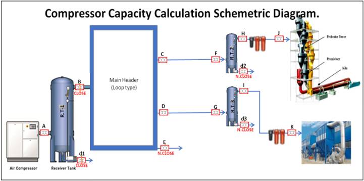
Capacity Assessment
Although the ideal method is standard calibrated nozzle method, wherein the nozzle is used as load (user) to vent out the generated compressed air. But this method is not frequently used at shop floor due to its complexity, need for a set of special nozzles, various measuring instruments etc.
At shop floor PUMP UP METHOD also known as RECEIVER FILLING METHOD is generally used. Although this is less accurate, but still an acceptable comparison can be made through this method
Pump-Up Method:
Assumption: air compression perfectly Isothermal, which means temperature of compressed air is same as ambient temperature.
- Isolate compressor and its receiver used for test, so that compressor can fill only this receiver and there is no flow out from receiver.
- Drain out all condensed water through drain valve and close it tightly for the test.
- Start the compressor and start the stopwatch.
- Record the time taken to attain normal operational pressure P2 (in the receiver) from initial pressure P1.
Use the following formula to calculate FAD capacity.
Actual Free air discharge
Qf =[(P2-P1)V]/[P0xT] Nm3/min.
Where
P2 = Final pressure after filling (Kg/cm2 a).
P1=Initial pressure after bleeding (Kg/cm2 a).
P0=Atmospheric pressure (Kg/cm2 a).
V=Storage volume in m3 which includes, after cooler and delivery piping.
T=Time taken to reach pressure from P1 to P2.
CORRECTION: In case compressed air temperature is t1 different from ambient temperature t0, the AFAD is to be multiplied by the below correction factor.
t.c.f =(273+t0)/(273+t1).
Example 1:
Compressor with rated capacity of 15m3/minute @ 7Kg/cm2 (for given altitude) is run for capacity assessment by Pump-Up method gives following readings. Calculate actual FAD and give suggestions for further investigation.
Receiver Volume=8 m3
Additional hold-up volume,
i.e., pipe/water cooler etc.,=0.5m3
Initial Pressure P1=0.5 Kg/cm2 (a)
Final Pressure P2=7.0 Kg/cm2 (a)
Atmospheric Pressure P0=1.025Kg/cm2 (a)
Time taken to build up pressure T=4.2minutes
Solution:
Total Vol. V=8+.5=8.5m3
From Pump-up method
Qf=[(P2-P1)V]/[P0xT] m3/min.
Therefore
Qf =[(7-0.5)8.5]/[1.025x4.2] m3/min.
= 12.83 m3/minute
Capacity shortfall with respect to 15 m3/minute rating is 2.17 m3/min i.e., 14.5%. indicating that compressor performance needs to be investigated further.
Isothermal Efficiency:
Isothermal efficiency = Isothermal Power / Input Power(shaft Power)
Isothermal Power (KW)= P0x Qfloger/36.7
Therefore
Isothermal efficiency
=[ P0x Qf x loger/36.7)]/Shaft Power.
P0=Absolute intake pressure Kg/cm2
Qf= Free air delivery m3/hr.
R=Pressure ratio (P2/P0).
SPECIFIC POWER CONSUMPTION
=Power consumption, KWhr (Motor power) / Free air delivery, m3/hr
Leakage test Procedure:
- Shut off all compressed air end-use.
- Run the compressor(s) to reach unload pressure P2.
- Start stopwatch as the compressor stops/unloads at unload- pressure P2 till pressure decreases to loading pressure P1, note this time (unloading time) and continue recording time till compressor stops/unloads again at unloading pressure P2.
- Repeat this 8-10 continuous cycles to get better average values of loading time “T” and unloading time “t”
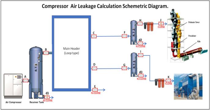
The system % leakages can be calculated as:
% leakage= 100T/(T+t)
(Or) System leakage quantity (m3/min),
q= % leakage x Actual free air delivery, Q
Ie. q= TQ/(T+t).
Example 2:
Compressor with actual capacity of 14m3/minute @ 7Kg/cm2 (for given altitude) is running for air circuit leakage test gives following readings.
Loading time T=2.2 minutes
Unloading time t=7.3 minutes.
Calculate leakage percentage, and losses.
Solution:
Using above formola
% Leakage= 100T/(T+t)
i.e., % Leakages=100 x 2.2/(2.2+7.3)
=23.16%
Leakages are quite high, so are optimization opportunities. Hurry-up!!!!
Air Consumption Calculation:
Floor Method to calculate actual consumption of any sub-section/end-use like bag filters, Air canons, instrument air etc.
CASE I:
If end-use like bag-filters, air cannons etc has individual receiver sufficient to supply air for 5-10 minute, we can directly use the method as used to find actual free air delivery in reverse sense, in this case it will become “pump-down method” to find air delivery rate or consumption rate.
i.e, Air consumption at pressure P
=[(P1-P2)V]/[P0xT] Nm3/min.
Such that( P1+P2)/2=P
Note:Actual Air consumption rate= Air consumption at pressure P-Leakages at pressure P.
Where
P2 = Final pressure after time T (Kg/cm2 a).
P1=Initial pressure at T=0 (Kg/cm2 a).
P0=Atmospheric pressure (Kg/cm2 a).
V=Storage volume in m3 which include, Receiver tank and delivery piping.
T=Time taken to reduce pressure from P1 to P2.
CASE II:
If end-use like process air, cooling air for instruments etc has receiver insufficient to supply air for about 5-10 minutes, we can directly use the method as used to find the leakages method to find air consumption as under.
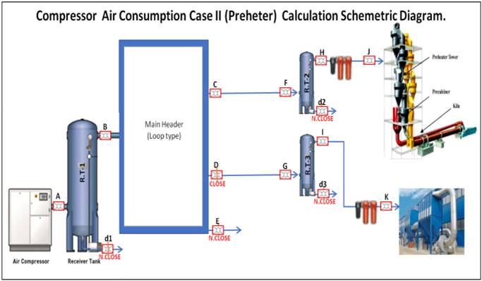
- Close all branches of other sections/users at main line and check leakage of the section of interest by using leakage method.
- Open end user/section of interest
- Run the compressor(s) to reach unload pressure P2.
- Start stopwatch as the compressor stops/unloads at unload- pressure P2 till pressure decreases to loading pressure P1, note this time (unloading time) and continue recording time till compressor stops/unloads again at unloading pressure P2.
- Repeat this 8-10 continuous cycles to get better average values of loading time “T” and unloading time “t”
The system consumption rate of considered
Section in m3/min will be:
qs= TxQf/(T+t).
Where Q is actual free air delivery.
Note: Calculate first leakages of the same section by closing valve to user to subtract it from above flow value to find actual compressed air consumption.
Optimization of Compressed Air System:
Optimization of compressed air system needs to take care of both the sides equally, the supply side and the demand side. The supply side consists of compressors (fixed rpm or variable rpm), air treatment equipment, primary storage and control system. While as the demand side consists of distribution piping, secondary storage, online treatment equipment and end user. Various optimization strategies are briefly discussed here. For details please go through my published paper “Optimization of compressed air in cement industry” in world cement magazine Issue June 2017.
Location of compressor: For every 10 oC rise in temperature of intake air will increases energy consumption of compressor by 2.5% for the same output.
Intake air filter: For every 250 mmwc of pressure drop increase across at the suction path due to chocked filters etc. the compressor power consumption increases by about 2% for the same output.
Inter cooler ,After cooler, Dryer and drainage: Efficient operation of inter cooler, after cooler, dryer and moisture traps are essentially important to ensure moisture free compressed air supply to instruments, tools located upstream without the need of an additional dryers, drain points which in turn consumes significant energy and introduces pressure drop in air distribution system.
Reduction of delivery pressure: Reduction in delivery pressure by 1 bar in compressor would decrease the power consumption by 6-10 %.
Compressor modulation by Optimum Pressure Settings: For similar compressors in group only one should be modulated to handle load variation and all others must be operated at full load. For different types of compressors in a group the one with minimum part load may be modulated. For different capacity compressor in a group, smallest one should be set to modulate. In general, the compressor with lower part load power consumption should be modulated.
Minimum pressure drop in Distribution lines: The acceptable pressure drop in industrial practice is 0.3 bar in mains header at the farthest point of use.
Segregation of low and high pressure applications: For low pressure end users compressed air should be preferably generated separately instead of reducing the pressure by reduction/regulator valves, which invariably wastes energy.
Avoid miss use of compressed air: Discourage compressed air use for the applications where actually a moving air will serve the purpose like floor cleaning, cooling instrument and bearings, body cleaning. Wherever safety provision allows use electric operated tools instead of pneumatic tools.
Avoid Compressed air leakages: Here is the biggest and best opportunity to save energy in compressed air system. In most of the industries 15-30 % of energy can be saved by properly arresting of air leakages in compressed air system. Method to find leakages is already discussed.
Conclusion: Periodic and punctual assessment by using shop floor methods and routine maintenance of compressor and compressed air network is essential to ensure optimized production cost and early attempt to harvest optimization opportunities. So, it is recommended highly to audit your compressor section/network by an expert once and follow the standard operating procedures to sustain a controlled optimum operation.
Bibliography:
- Ivor F. da Cunha P.Eng of Leap Frog Energy Technologies Inc.
For the CEA Technologies Inc. “COMPRESSED AIR Energy Efficiency Reference Guide”
- Book-3 Bureau of energy efficiency, India
For National Certificate Examination for Energy Managers and Energy Auditors “Energy Efficiency in Electrical Utilities”
*****THANKS A LOT, PLEASE SHARE YOUR OPINION ABOUT THIS ARTICLE IN COMMENT*******
Leave a Reply